|
The light corona
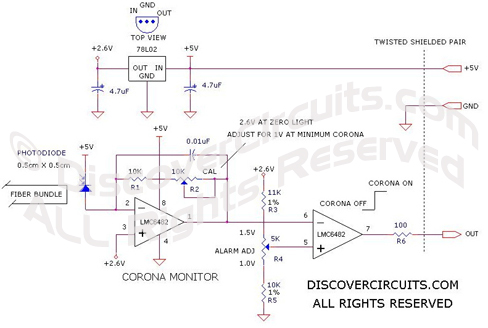
monitoring and alarm circuit I designed is pretty simple. The
circuit is powered by +5v and has an on-board voltage regulator as a
reference voltage. The current from a reversed biased
photodiode is converted into a voltage using an op Amp circuit.
That output voltage is fed to a voltage comparator circuit. I
included an adjustment in the current to voltage converter.
After setting the gain to produce a one volt output signal for a
typical corona discharge, the comparator’s threshold voltage could
also be adjusted. The device then changes states when the
corona intensity dropped by about 20%.
The alarm output of
the monitoring circuit is connected to the company’s computer
through a three pin connector. The alarm signal controlled the
treatment process. When the computer sensed the corona alarm
signal, it would shut down the system. A human operator would
then back up the plastic film a few feet and rethread it into the
take-up rollers. Finally, he would press the reset button,
which told the computer to start up the film treating process again. |